![]()
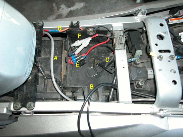
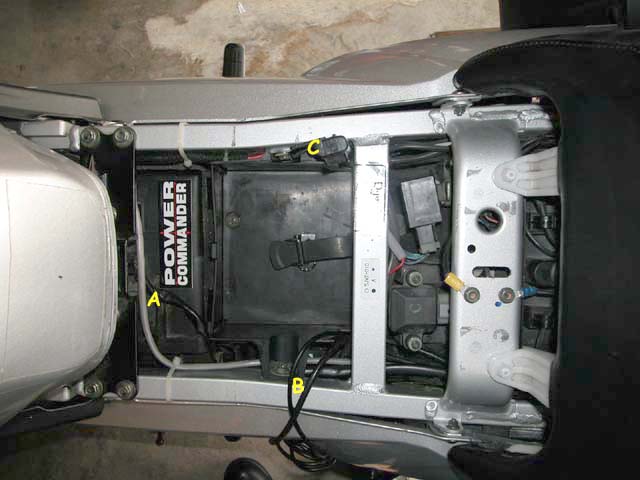
| Power Distribution Block In the Fall (10/02) and after a week of rain had just passed (a direct result of the bad mojo called down from washing and waxing the bike) I knew I needed to wire the bike for my Widder heated gear. The battery and fuses are not hard to get to, but there are the easy-access of 10 years of Wing ownership has spoiled me. I wanted to work up some sort of "sub-panel" that would be easy to get to when adding electrical accessories and when needing to check fuses. I came up with this power distribution panel. I original ran it where I could get to it underneath the riders seat.
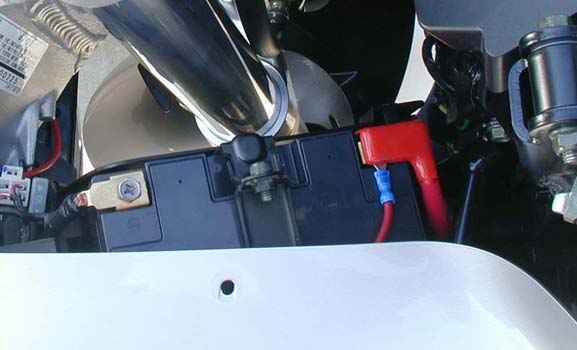
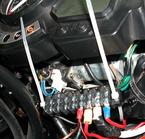
The photo of the battery area shows the simplicity and clean install of the single feeder line to the sub-panel It worked very well over the next year, but there were some improvements that I wanted to make. A year later (10/03), I wanted to regain the storage under the seat, to better protect the power distribution block (PDB) from anything that might short it out, to add the functionality of a circuit that was switched with the ignition as well as the original, "always on" circuit, and I wanted to clean up all the wires that had found their way back to the battery terminals. I started with yet another great tech tip by Dale Wilson and expanded on it. To do everything I wanted to do, I ended up pulling out all the accessory circuits I had installed over the past year (Jastek outlets, GPS, V1, PIAA 910's, CB, Datel voltmeter, Magnum Blaster horns, and others). I installed a 30 amp relay to a second PDB and mounted the left PDB up under the left front dash cross member.
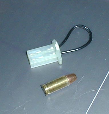
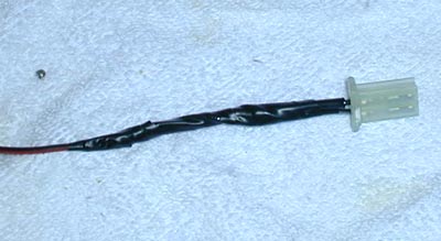
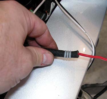
I used the tips at FJR Info & this site to disable the auto-retract function of the shield. Instead of leaving the connector stuffed in the wiring bundle, you can use it to make a power "feeder" for your switched PDB relay.
I then used the jumper to fabricate a power connector that feeds the relay energizer circuit so that this PDB would be switched on along with the ignition.
Just snip the loop in half, plug the connector back in like it was before removal, and use a volt meter to dope out which half of the loop gives you +12 volts. The side you want to use will have power when the ignition is on and won't when you turn off the ignition. Just seal off (tape, etc.) the other side of the loop that you don't use. In the example above, it's under the electrical tape (insulated from the wire soldered to the +12 side of the loop). Using this OEM connector means you don't have to cut into the bike's wiring harness.
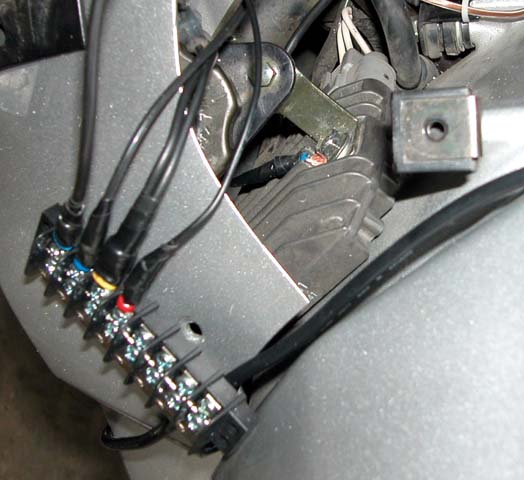
The right PDB was installed the same way, but without the relay so that the circuit is always hot. Each main feed used a 30 amp fuse.
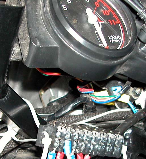
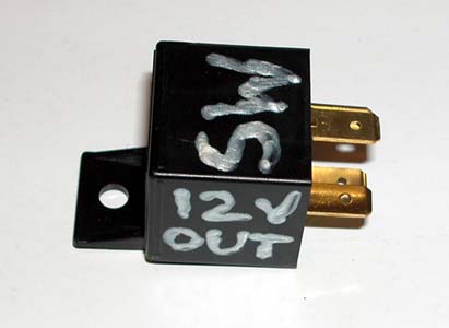
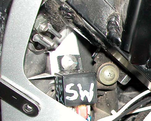
Before installing the relay, I clearly marked it to ease roadside trouble shooting. I then mounted it to the upper fairing retaining fastener as shown in this photo.
I also installed a ground bar that runs back to the negative terminal of the battery.
I originally anchored it to the frame (sharing the same retaining bolt as the regulator/rectifier) but I got a lot of alternator hum through my audio gear. This is because the FJR uses a charging system that shunts excess power to the frame. Grounding electronics to the frame (floating ground) then picks this up and causes the hum.
The end result was a tool tray that was free of clutter, one switched PDB, one unswitched PDB, and a ground block. I also used a trick, learned years ago, that takes combinations of wire ties (1, 2, 3, etc.) on both ends of each circuit so that tracing a run of wires is be easier.
All material on this site (c) 1995 - Present, Mark Johnson. All rights reserved. |